Table of Contents
Objective: Learn how to create a basic statechart and run it.
Previous Tutorials: Create a "Hello World!" Component in ArmarX (C++)
Next Tutorials: none
Reference Code: statechart_tutorial
This tutorial will guide you through the process of creating a running program within the ArmarX framework. Programs in ArmarX can be designed as statecharts. They consist of states and transitions between these states. Defined events can cause the program to transition from one state to another. To design statechart programs in an easy and clearly represented way, ArmarX provides a graphical statechart editor. We will make use of this tool.
In this tutorial, we will implement a simple counter. To actually count, a counter state will increment a counter by one, then transition to itself, increment the counter again and so on until a maximum value is reached. The program will then transition to an end state and terminate. You will be able to verify the correct execution of the program via the ArmarX log.
The goal of this tutorial is to give you an overview about what it takes to develop a program in ArmarX using the statechart editor. You will also get an understanding of the statechart concept.
Create a new ArmarX Package
Create a new package called, e.g., statechart_tutorial:
Getting Started
Start Ice and ArmarX GUI
Open the Statechart Editor
Once you start ArmarX GUI, you get the "ArmarX GUI Use Case Selection". Here, you can click on the option "Armar3 Statechart Programming" that will automatically open the correct GUI profile for this tutorial. Then, you can jump to the next section "Start Creating Your Statechart".
Otherwise, you can choose "Open empty GUI" and open the statechart editor manually from the "Add widget" menu. This is a slower option right now, but later on you may need to open the statechart editor using this option.
To manually open the statechart editor, goto "Add Widget" and select "StatechartEditor" in the drop-down menu. The current version of the StateChartEditor might look a little bit different compared to the following images, but the essential structure should stay the same.
Finally, you can also open the statechart editor by pressing the
icon in the top-left corner
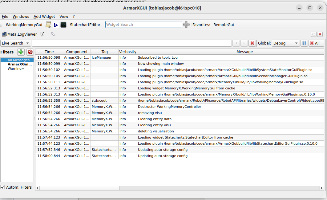
After opening the statechart editor, you are prompted with a dialog that requires you to select a profile on which you want to work. For further information about Statechart Profiles, see Statechart Profiles. In case you have a minimal installation it looks as follows:
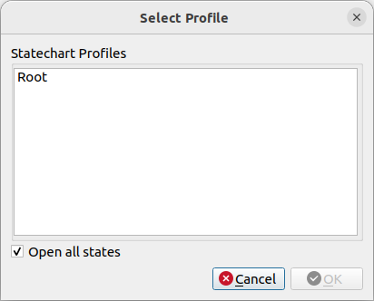
In case you have at least one robot project installed it looks similar to this:

For this tutorial, choose any of the Armar3 profiles or the Root profile. (The Root profile shows up if you have no robot projects installed and thus, no profiles can be found.)
Create the Statechart
First, we have to create a statechart group. Then, we create the actual states and their implementation.
Create a new Statechart Group
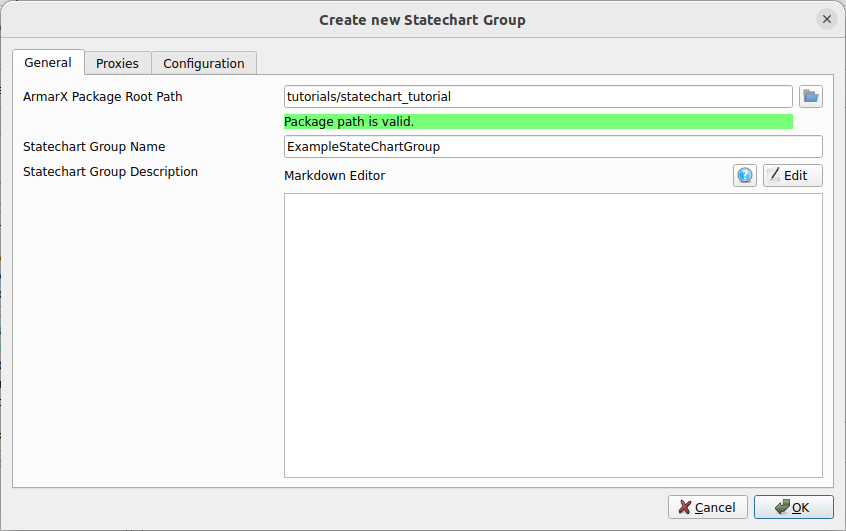
Create a new statechart group by pressing the "New Statechart Group" button (the one on the far left with the little green plus).

Switch to the "General" tab, select the directory of your ArmarX package statechart_tutorial, (tutorials/statechart_tutorial if you followed the commands above; the path can be relative to $ARMARX_WORKSPACE), and enter a group name, e.g. ExampleStateChartGroup.
Is not necessary that the name of a statechart group ends with
Group. However, it is a convention and can avoid name conflicts with states.
Now the statechart editor is readily set up and we can start implementing our statechart-based program!
Add States to the Statechart Group
Create the Main State
Our final program will implement a state machine consisting of three states:
- A main state,
- a counter state and,
- an end state.
The main state represents the whole statechart and will house the other two states as substates. The counter state will do all the work (counting) and trigger a transition to the end state when done. The end state will terminate the program.
See ArmarX Statecharts for more information on statecharts.
First, we will only set up the main state and the counter state. We will look into creating the end state a little later.
Please note that all state names, parameter names, event names etc.
are case-sensitive.
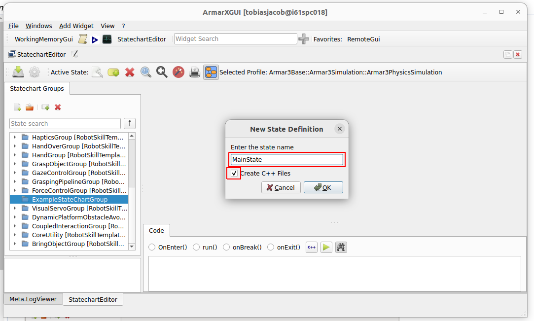
To create the main state: 1. Select our statechart group. 2. Click on the other button with a green plus (next to smaller button with the red X).

In the dialog that opens, enter the name MainState, select "Create C++ Files", and confirm.
Right click on MainState and check "Public State" to make the state public. This allows to run the state itself as initial state, or from other statechart groups.

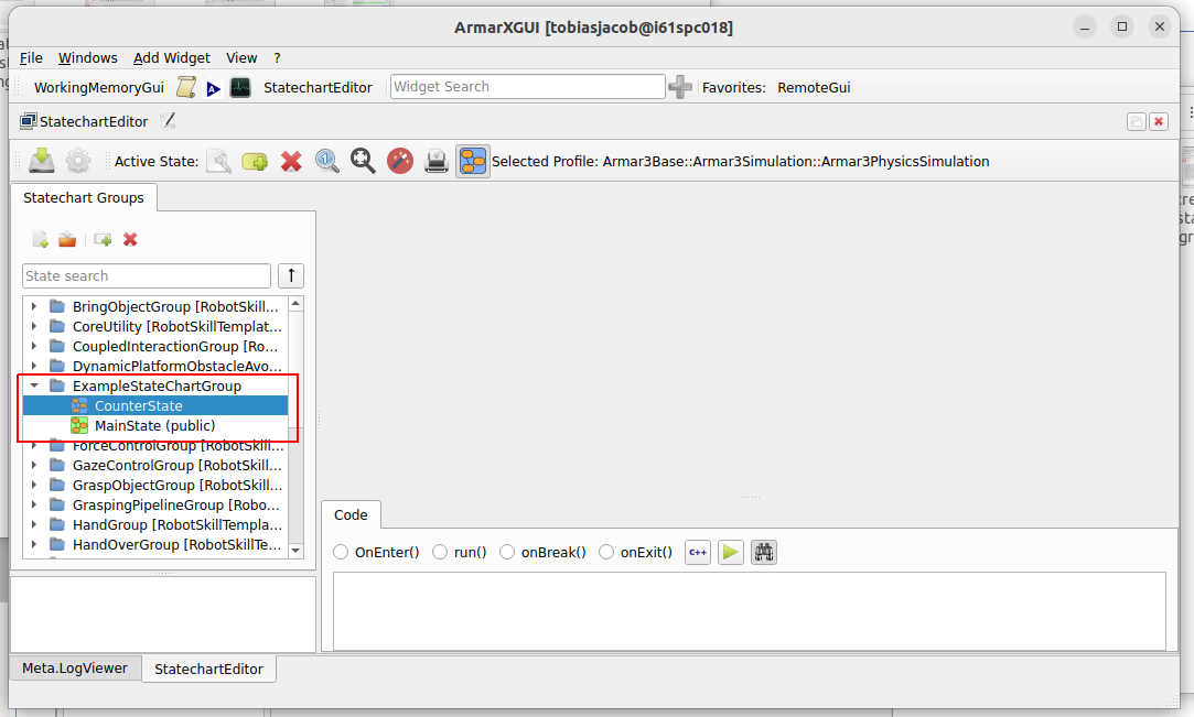
In the very same way, create a second state called CounterState. The counter state, however, does not need to be public. Do not forget to select Create C++ files again.
In the end, it should look like this.
Go ahead and save your work by clicking on the "Save All" button with the

icon in the top-left corner of the statechart editor.
Edit the Main State
Now that we have created our states, we will need to edit them. There are two ways of editing states, both of which we will need and learn in this tutorial:
- Some edits can be made right in the GUI, e.g. defining parameters.
- Others will need to be made in the C++ source code of the states, e.g. define the actual state behavior.
We will start by editing the main state directly within the GUI. To open the main state, double-click on its name. A blue shape will appear in the right section of the editor, representing the main state. Note that by default, all states contain the substates Success and Failure, indicating how the execution of that particular state ended. Another default behavior is that the starting state of all newly-created states is Success; we will change that in a bit. Both Success and Failure act as explicit end (sub-)states for that particular state, as indicated by their yellow color. If any end substate is ever reached, the state that houses it is considered to be finished.

To start editing the main state, right click in the blue surface and select "Edit State MainState".

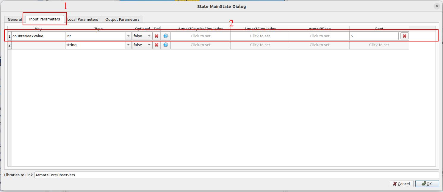
The main state will have one input parameter and one local parameter:
- The input parameter will be the value up to which the counter should count.
- The local parameter will be a reference to the current value of the counter.
To configure our input parameter counterMaxValue, choose the tab Input Parameters and edit the Root profile so that it looks like this image:
- Note
- By providing 5 as value in the Root profile, we define a default value for the parameter
counterMaxValue. You might be asking yourself why we do not mark counterMaxValue as optional, since we provide a default value for it. However,optional=truemeans that we may not want to work with the parameter at all and will want to check whether it is defined by the caller, whileoptional=falsemeans that we always want to work with the parameter (like in this case), so the value has to be always supplied by the caller, or by using a default value. It is rarely necessary or appropriate to set optional to true, so do not worry about it too much.
Quite similarly, edit the local parameter counterId, and press "OK".
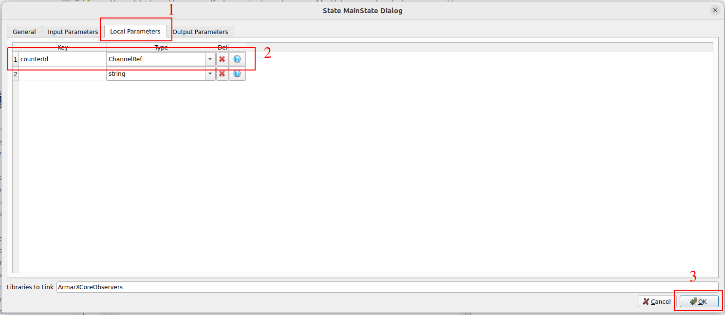
You may wonder why the type of counterId is armarx::ChannelRef. We will come to this shortly.
To automatically update the state's layout, you can right-click on it and press Layout state.

Edit the Counter State
In a very similar way, we are now going to edit the counter state. Via drag & drop, drag the counter state from the tree on the left of the editor window into the main state. It will appear as a smaller blue box within the MainState. It, too, starts with the substates Success and Failure, the former of which is once again the starting substate.
Your statechart editor should now look like this:
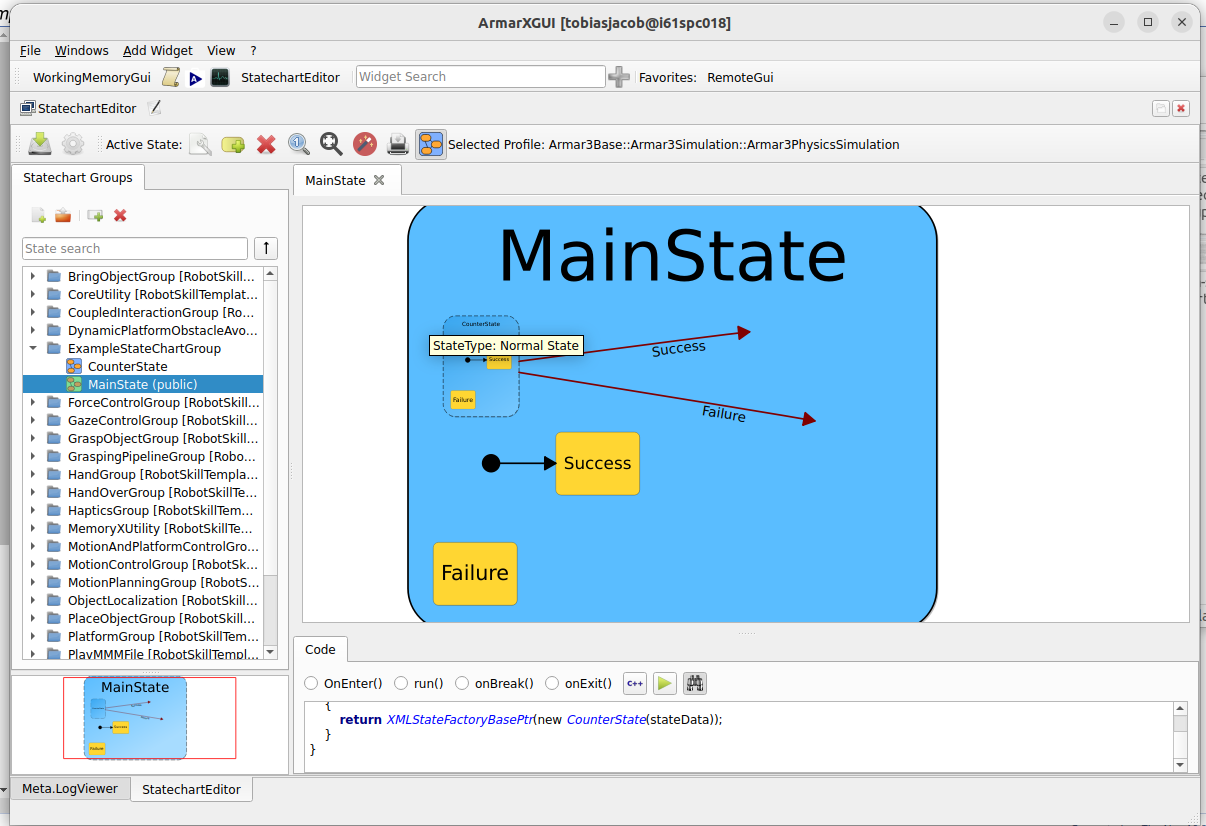
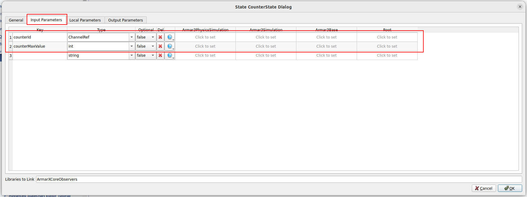
Just as we edited the parameters of the main state, we will now edit the parameters of the counter state. It will only have two input parameters that it gets from the main state: One will be the maximum value of the counter and the other one the reference to the current counter value.
Moreover, we will define events that can trigger transitions from the counter state to other states.
To edit the counter state, right click on its blue shape and select Edit State CounterState. Edit the input parameters as shown in the following image:
The counter state will increment the current counter value by one each time it is entered. It will then have two transition options: One will be triggered if it has not yet reached the value it is supposed to count up to. This transition will bring the program right back to the counter state. The other transition will be triggered if the counter has actually reached the maximum value, and consequently bring the program into the end state.
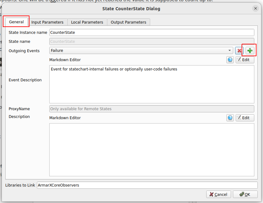
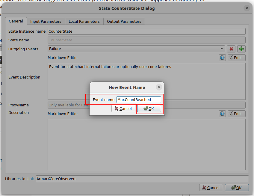
To create these two transitions, we will now define outgoing events in the counter state that trigger our transitions. Therefore, chose the tab General, click on the green plus and name the new event MaxCountReached. Do the same to create the second event, MaxCountNotReached.
Once done, the statechart should look something like this:
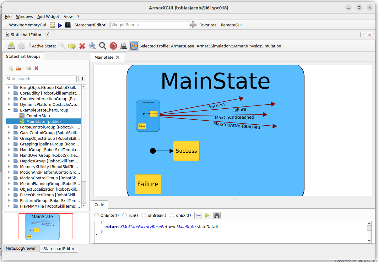
Edit the Substates
While recovering from failure (for example, exceptions during execution) is a very useful feature, for the sake of simplicity, we will omit any sort of error handling. This means that we do not need the Failure State of the CounterState, and it can be safely deleted (right-click on the state and select "Delete State").
You will notice that CounterState still has its default Success State, which is even its starting state. We have already defined the Event MaxCountReached, which is sent when we are completely done with CounterState and implies successful execution up until now. MaxCountReached is also more descriptive, so we do not need CounterState's Success state, and you can delete is as well.
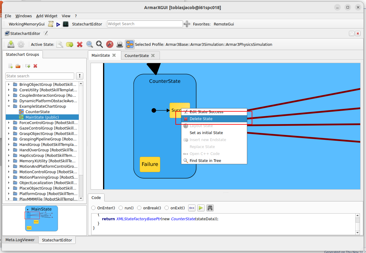
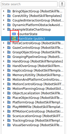
To mark CounterState as a leaf-state, it is very important to delete both the Success and Failure state. If there are no internal substates, no initial state has to be set.
Despite deleting the failure state, it will keep the Failure transition, as it is always necessary. So it is a very common procedure for creating a leaf-state to delete all substates, and then create all additional success transition types next to the failure transition. Note how the icon of the CounterState changes as well.
Connect the Transitions
First, you'll want to set CounterState as the statechart's initial state, do so by right-clicking CounterState and selecting Set as initial State.

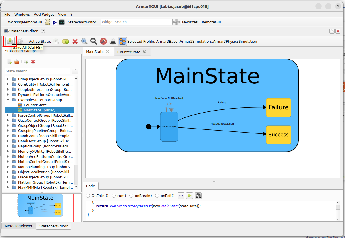
The two red arrows that represent the transitions that we've just created are not connected yet. To tell the statechart editor where these connections should lead to, we have to drag their tips to the respective state. By doing so, connect the MaxCountReached arrow to the final state Success and the MaxCountNotReached arrow back to the counter state. You can connect the Failure to the failure state. The connections should now look like this:

Don't worry if the arrows look messy. Just click on the "Layout state" button to automatically arrange the layout.
Edit the Transition Properties
The last thing we can edit directly in the GUI of the statechart editor are the transitions. Now the transitions know from where to where they go, but they still need to know which parameters they should pass between the states.

Now we will tell the transition to pass both parameters of MainState to CounterState by editing the dialog box, accordingly. When you are confident that your dialog looks exactly as shown in the following screenshot, hit the OK button.

Repeat the step for the MaxCountNotReached transition.

Hit Crtl + S or Save all to generate the code.
Editing the Source Code
After all we did so far, our statechart looks pretty good. However, there are some modifications we still need to do before we can run the program. The counter state, for example, does not even know how to count yet. These modifications will need to be implemented in the source code of the states.
Before we go on, do not forget to save your statechart with "Save All" again.
Next, boot up your favorite C++ IDE. For example, follow How To Set up QtCreator for ArmarX on how to use QtCreator.
In the IDE, open the package at ${ARMARX_WORKSPACE}/tutorials/statechart_tutorial/. In QtCreator:
- Select
Open File or Project ... - Open the top-level
CMakeLists.txtat${ARMARX_WORKSPACE}/tutorials/statechart_tutorial/CMakeLists.txt - When configuring the project,
- Uncheck "Imported Kit"
- Check "Axii's Kit"
- Press "Configure Project"
- Uncheck "Imported Kit"
- If the project fails to load (notable from the small yellow warning sign), you need to change to correct build type. Most of the time, this is "Release with Debug Info" To do this:
- Option 1:
- On the left hand-side, press "Projects"
- In the top center, find the drop-down menu next to "Edit build configuration"
- Change it to the correct build type (usually "Release with Debug Info")
- Option 2:
- In the lower left corner, press the big button saying "statechart_tutorial" and "Debug" ("Debug" is the wrongly selected build type)
- In the "Build" column of the panel that pops up, choose the correct build type (usually "Release with Debug Info")
- Option 1:
- Now, QtCreator should correctly load the project and show its structure.
Here is a list of useful shortcuts when working with Qt Creator:
| Shortcut | Description |
|---|---|
| Ctrl + Click | Follow symbol (mostly works) |
| F2 | Follow symbol under cursor |
| F4 | Switch between header and cpp file |
| Alt + Left | Go back |
| Alt + Right | Go forward |
| Ctrl + K | Find symbol (Like Ctrl + , in Visual Studio) |
| Ctrl + W | Close current file |
Take a look at MainState.h
Before we add any code, let us take a look at MainState.h. As you can see the MainState class is derived from MainStateGeneratedBase<MainState>, which is defined in the header MainState.generated.h.
Now open MainState.generated.h (Ctrl + Click or F2 on the included header in MainState.h). As the filename suggests, this file is generated by the statechart editor in the GUI and you will not need to make any manual changes. In fact, any manual changes are overwritten the next time you save your statechart in the editor.
If you take a close look at the contents you will notice the member variables in, local and out, which are of the types MainStateIn, MainStateLocal and MainStateOut. These provide us with convenient interfaces to access the input, output and local parameters we defined in the GUI. Now close MainState.generated.h again.
Edit MainState.cpp
We will need to register our counter in the code of the main state. Open the file MainState.cpp and have a look at the code. You will come across the function onEnter(), which is empty so far. We will make two changes to this function:
- First, we will add a log output that lets us keep track of the execution of the program. This change does not affect the functionality of the program.
- Afterward, we add some code to make the counter work (detailed explanation follows after the screenshot). This code is crucial for the program.
You can copy it from here:
The first line just prints MainState::onEnter() when the function is called. The second line is more interesting. Here, we acquire a channel reference on a counter that is provided by the armarx::SystemObserver. Our statechart is embedded in an armarx::StatechartContext, which provides access to different components and can be obtained by calling getContext<StatechartContextTemplate>() within any state. However, the generated state subclass provides convenience access functions to all proxies, e.g. this->getSystemObserver().
One of these components is the armarx::SystemObserver that provides timers and counters. By calling
we tell the SystemObserver to create a new counter with name counterId and initial value 0. We receive a ChannelRefPtr, which we can later use to access this counter again. In the third line of code we store this reference in the states local parameter counterId.
To learn more about Observers and Channels take a look at ArmarX Observers.
Edit CounterState.cpp
Last, we have to teach the CounterState how and what to count. Moreover, we tell it when to trigger which event. All this information is packed into the following code. Type it into CounterState::onEnter():
In the statechart editor we set the input parameter "counterId" of the CounterState to the value of the local parameter "counterId" of the MainState. Hence, we can now obtain the reference to the counter created in MainState::onEnter() via in.getcounterId().
The line getSystemObserver()->incrementCounter(counterId); tells the SystemObserver to increment the counter.
The SystemObserver offers the functionality for distributed counters and timers. A local counter would also be possible, but with a distributed counter, it is easy to check the current status of the counter online with the ObserverGui.
Next, we compare the current value of the counter to our maximal counter value. If the counter value exceeds the maximal value, we emit the event MaxCountReached, else MaxCountNotReached.
Open the CounterState.cpp file and insert the above code into the onEnter()-function.
Build the program
Finally, we can compile / build our package! All you need to do for building is hammering these lines of code into the console:
Alternatively, you can use QtCreator to execute these steps. Usually, it is sufficient to build via Ctrl + B or the hammer icon in the lower left corner. If not, via the menu choose "Build", then "Run CMake" followed by "Build", "Build Project statechart_tutorial".
Prepare to Execute Your Program
You already know how to import your package and the components into your scenario manager from Create a "Hello World!" Component in ArmarX (C++).
Now we can create our scenario via the scenario manager by clicking onNew Scenario.
Set the name of the new scenario to StartStateChart and select the previously registered package statechart_tutorial. To finish the creation press the OK button.

Drag our State Chart Group into the new scenario.
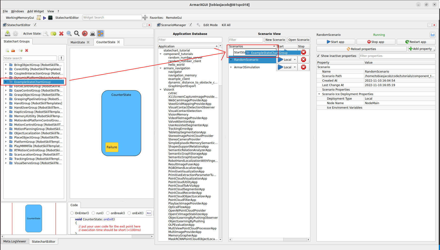
After you have added the statechart group you have to select the group in the scenario manager and set the property ArmarX.XMLStateComponent.StatesToEnter to MainState. This property determines which state of the group will be automatically entered upon startup.

Now use the application database in the scenario manager to search and add the two applications ConditionHandler and SystemObserver. You can add an application to a scenario using drag and drop onto the target scenario. These applications are required to execute our statechart.
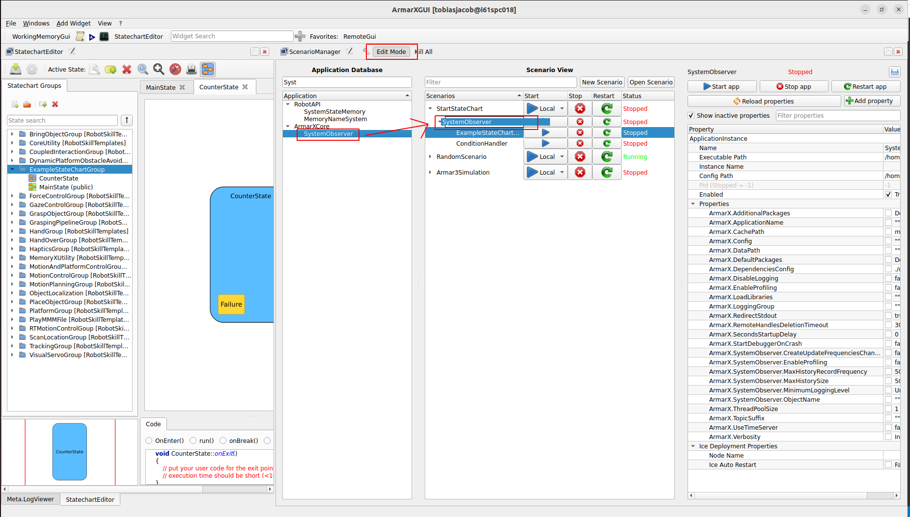
The applications ConditionHandler and SystemObserver provide components with the corresponding names. Both components are required by the statechart context and can be accessed from the other processes via Ice.
Execute your program
Finally, we can execute our program by pressing on of the two start buttons in the scenario manager.
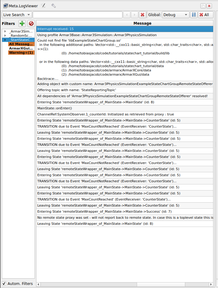
If something goes wrong, check the output via the Meta.LogViewer in the ArmarX GUI and check your statechart and scenario configurations. Remember to stop the scenario by pressing one of the two stop buttons.
Another way to start and stop a scenario is via the command line interface. To start our scenario use the following command
and to stop it use the very similar command
Note that you can start a scenario via the GUI and stop using the CLI and vice versa. Both methods are equivalent and can be used interchangeably. To get more information about the CLI you can use the help command.
What will happen during the scenario is exactly what we intended: The CounterState will increment the counter. If the maximum value is not yet reached, it will transition to itself and keep on counting. Once the maximum value is reached, the program will transition to the end state and terminate. You can see what your program did in the console output. Note the following expressions
and
- In the Meta.LogViewer, you should see output that includes similar lines given in the following:
Congratulations you built your first ArmarX StateChart!
