Table of Contents
In this tutorial, advanced visualization features are explained. It is shown how the DebugDrawer (and an extended version, the EntityDrawer) is used and how the layered visualization can be dispalyed in several ArmarXGui plugins.
Getting Started
For this tutorial, you need following prerequisites:
- A copy of ArmarX including RobotAPI (containing the DebugDrawer component), ArmarXGui (to visualize the drawings), and optionally MemoryX (containing the EntityDrawer that can be used to display objects from the memory).
Create your own package
If you already have a package in which you would like to add this tutorial, go to the next step Generate template files of your new component and a test application.
In order to create a new ArmarX package called "RobotComponentTutorials", execute the following code in the directory where you want to make your package,
or you can use "-d" option to specify the directory.
Generate template files of your new component and a test application
Execute the following commands in the toplevel directory of your package. All required files for the component and the test application will be generated.
Have a look into the directory to check if everything worked as intended. You should find the following files:
Start Implementing
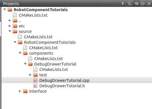
- First, we load the component to the QtCraetor IDE (as described in Tutorial: Counting with Statecharts -> Edit the source code). You should have a project similar to the following setup:
- Add the following line into the CMakeLists.txt at the top-level directory of your project. depends_on_armarx_package(RobotAPI)depends_on_armarx_package(MemoryX "OPTIONAL")
- Edit the CMakeLists.txt file in your DebugDrawerTutorial component directory.
- Add the following dependencies find_package(Eigen3 QUIET)find_package(Simox ${ArmarX_Simox_VERSION} QUIET)armarx_build_if(Eigen3_FOUND "Eigen3 not available")armarx_build_if(Simox_FOUND "Simox-VirtualRobot not available")include_directories(SYSTEM ${Eigen3_INCLUDE_DIR})include_directories(${Simox_INCLUDE_DIRS})
- Add the library set(COMPONENT_LIBS ArmarXCoreInterfaces ArmarXCore RobotAPICore ${Simox_LIBRARIES})
- Add the following dependencies
- Edit DebugDrawerTutorial.h
- Add includes
- Add DebugDrawer Proxy protected:armarx::DebugDrawerInterfacePrx debugDrawerPrx;
- Edit DebugDrawerTutorial.cpp
- Offering the debugDrawer topic void DebugDrawerTutorial::onInitComponent(){// writing to the DebugDrawer topic. In ArmarX this topic's default name is DebugDrawerUpdatesofferingTopic("DebugDrawerUpdates");}
- Get the proxy and draw a coordinate system void DebugDrawerTutorial::onConnectComponent(){// retrieve the proxy to the debug drawerdebugDrawerPrx = getTopic<armarx::DebugDrawerInterfacePrx>("DebugDrawerUpdates");// setup a 4x4 homogeneous matrixp.setIdentity();// set x,y,z coordinates (mm)p(0,3) = 0.0f;p(1,3) = 500.0f;p(2,3) = 1000.0f;// draw the posedebugDrawerPrx->setPoseDebugLayerVisu("MyPose", p_global);}
- Offering the debugDrawer topic
Setup an application to test the component
- Update the application's /source/ddtest/applications/DebugDrawerTest/CMakeLists.txt find_package(Eigen3 QUIET)armarx_build_if(Eigen3_FOUND "Eigen3 not available")include_directories(SYSTEM ${Eigen3_INCLUDE_DIR})set(COMPONENT_LIBS ArmarXCoreInterfaces ArmarXCore DebugDrawerTutorial)
At this point, the package should compile without any errors. To make sure it does so, first run CMake and then build the package.
- Update the application's /source/ddtest/applications/DebugDrawerTest/CMakeLists.txt
Show the DebugLayer in ArmarXGui
The debug layer is implemented in several gui plugins (currently the DebugDrawerViewer, WorkingMemoryGui, RobotViewerGui) and in the Viewer of the DynamicSimulator. In the following example, we show how to start the kinemtic simulation of Armar3 in order to show the debug layer of the RobotViewer gui plugin.
- First, we start a robot simulation (in a separate terminal shell), e.g. the RobotAPI scenario KinemticSimulationArmar3 cd ${ArmarX_DIR}/RobotAPI/scenarios/KinematicSimulationArmar3./startSceanrio.sh
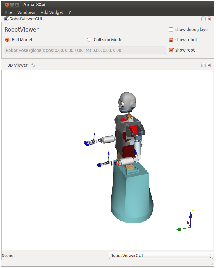
- Now, we can start the ArmarXGui and load the RobotViewer Select AddWidget->RobotControl->RobotViewerGUI and configure as shown below.armarx guiThe gui plugin with some options and the Armar3 robot should be visualized as follows

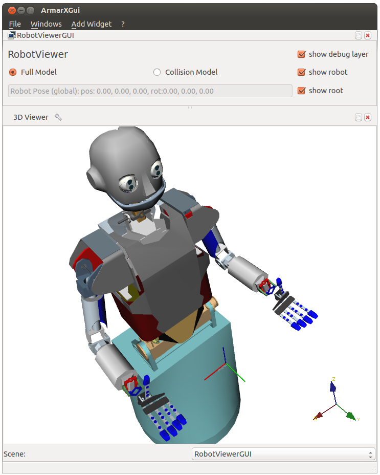
- The demo application is started in order to paint on the debug layer: Then, the coordinate system should show up in the ArmarXGui 3D visualization as follows:${ArmarX_DIR}/RobotComponentTutorials/build/bin/DebugDrawerTutorialAppRun
- Now you can safely stop the example by pressing <ctrl>-c in the shell where you started the DebugDrawerTutorialAppRun. The visualization remains until it is updated or the gui plugin is started again.
Advanced Drawing Capabilities
Now we want to dispaly some more graphics. Therefore, we add periodic task to continously update the visualization.
- Edit DebugDrawerTutorial.h
- Add includes
- Add run method and periodic task object protected:void run();armarx::DebugDrawerInterfacePrx debugDrawerPrx;PeriodicTask<DebugDrawerTutorial>::pointer_type task;
Edit DebugDrawerTutorial.cpp
- Setup and start the periodic task void DebugDrawerTutorial::onConnectComponent(){// retrieve the proxy to the debug drawer and clear itdebugDrawerPrx = getTopic<armarx::DebugDrawerInterfacePrx>("DebugDrawerUpdates");debugDrawerPrx->clearDebugLayer();try{task = new PeriodicTask<DebugDrawerTutorial>(this, &DebugDrawerTutorial::run, 10, false, "DebugDrawerTutorialTask");task->start();}catch (...){ARMARX_WARNING << "Failed to start DebugDrawerTutorial task";}}
- Implement periodic run method void DebugDrawerTutorial::run(){// setup a 4x4 homogeneous matrixp.setIdentity();// set rotating coordinates (mm)p(0,3) = sin(clock() / 10000.0)*200;p(1,3) = 500.0f;p(2,3) = 1000.0f + cos(clock() / 10000.0)*200;// size of the box in mmEigen::Vector3f v(100,100,100);// draw/update red boxdebugDrawerPrx->setBoxDebugLayerVisu("MyBox", p_global, s, DrawColor {1, 0, 0, 1});}
- Stop the run() method when the component gets disconnected: void DebugDrawerTutorial::onDisconnectComponent(){task->stop();}
- Implement periodic run method
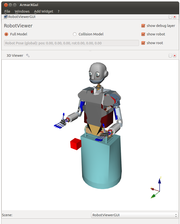
When starting the application again you should see a rotating box
- Add some more visualizations The following list is an exerpt from the DebugDrawer's slice definition file (DebugDrawerInterface.ice) and shows several visualization features you can play around with.
- Pose (Coordinate systems) setPoseDebugLayerVisu(string poseName, PoseBase globalPose);setScaledPoseDebugLayerVisu(string poseName, PoseBase globalPose, float scale);
- Line void setLineDebugLayerVisu(string lineName, Vector3Base globalPosition1, Vector3Base globalPosition2, float lineWidth, DrawColor color);
- Box void setBoxDebugLayerVisu(string boxName, PoseBase globalPose, Vector3Base dimensions, DrawColor color);
- Text void setTextDebugLayerVisu(string textName, string text, Vector3Base globalPosition, DrawColor color, int size);
- Sphere void setSphereDebugLayerVisu(string sphereName, Vector3Base globalPosition, DrawColor color, float radius);
- PointCloud void setPointCloudDebugLayerVisu(string pointCloudName, DebugDrawerPointCloud pointCloud);
- Polygon void setPolygonDebugLayerVisu(string polygonName, PolygonPointList polygonPoints, DrawColor colorInner, DrawColor colorBorder, float lineWidth);
- Arrow void setArrowDebugLayerVisu(string arrowName, Vector3Base position, Vector3Base direction, DrawColor color, float length, float width);
- Cylinder void setCylinderDebugLayerVisu(string cylinderName, Vector3Base globalPosition, Vector3Base direction, float length, float radius, DrawColor color);
- Pose (Coordinate systems)
- Setup and start the periodic task
- Custom Layers
Until now, all visualizations have been drawn to the "debug" layer, which is a default layer of the DebugDrawer. You can add custom layers by specifying the layer string.
E.g. the callbecomesdebugDrawerPrx->setBoxDebugLayerVisu("MyBox", p_global, s, DrawColor {1, 0, 0, 1});You can clear your custom layer withclearLayer(string layerName); Add robot visualizations
A robot can be visualized in a network transparent way by the DebugDrawer. Edit the DebugDrawerTutorial.cpp as follows:
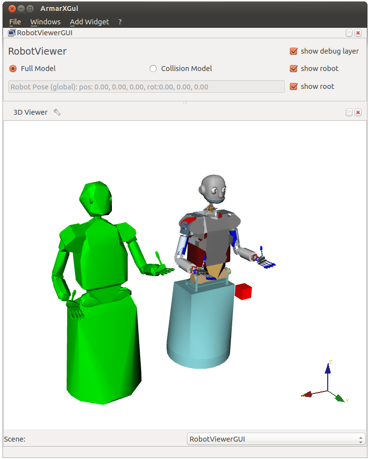
- Setup the robot in onConnectComponent() void DebugDrawerTutorial::onConnectComponent(){...// draw robot collision model (ArmarIII.xml in project RobotAPI)debugDrawerPrx->setRobotVisu("MyRobotLayer", "MyRobot", "RobotAPI/robots/Armar3/ArmarIII.xml", "RobotAPI", armarx::CollisionModel);// set position of robotp(0,3) = 1000;// set color to greendebugDrawerPrx->updateRobotColor("MyRobotLayer", "MyRobot", DrawColor {0, 1, 0, 1});}
- Update the configuration (joint angles) in the run() method
The result is a moving robot in the "MyRobotLayer" debug layer:
- Setup the robot in onConnectComponent()
Showing Objects from Memory
tbd...
